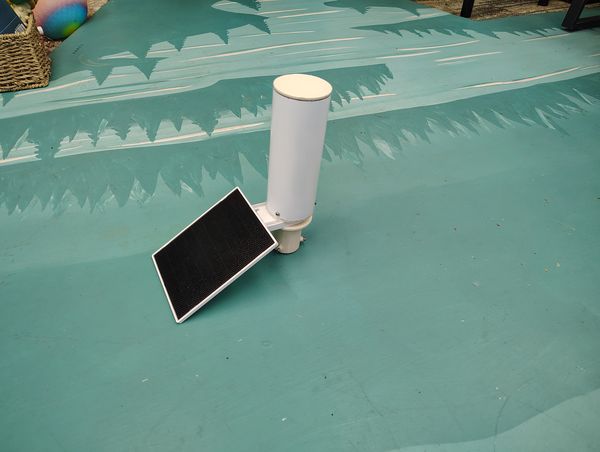
Assembled
Bottom Assembly minus LoRa mount and unit
Solar cell mount
Tap the hole in the base with a 1/4-20 tap.
If you don't have a tap, see the next sub step.
Bolt the arm appropriate for your approximate latitude to the base with
a 1/4-20 stainless steel bolt.
If no tap is available, drill the hole to 1/4 inch and assemble the
solar cell holder with epoxy, cementing the bolt into the hole. Additional epoxy at the mating surface will strengthen
the bond.
Cut the wire from the solar cell as short as practicable and feed it through the
provided hole.
The hole may need to be drilled out to 9/16 inch.
Don't cut the wire so short that it is difficult to solder later.
Bottom assembly
Insert the solar panel wire through the hole in the electronics mount /
bottom cap.
Align the holes in the base with those in the electronics mount / bottom
cap and stack the parts together
Align the hole in the pole mount with the hole in the other parts (see
the illustration above)
Bolt the bottom assembly together with a 3/4-inch 1/4-20 bolt and nut.
Place a bead of silicone caulk/RTV around the head of
the bolt
The correct adhesive should have a strong vinegar smell.
Insert the bolt from the electronics mount side, not the pole side.
This will take up minimal space allowing the electronics
mounting panel to insert deeply into the mount base
Cut the USB-C connector off the end of the cable
Leave sufficient length to solder to the cut ends. The USB-C
connector will be soldered back to the cable in the assembly.
These instructors are for the Heltec v3. See below for the
Heltec v4).
Leave enough length to have excess wire so that it is easy to handle
and plug into the LoRa electronics.
Use heat shrink tubing to insulate the solder joint (see the
procedure in the fascia-mounted repeater).
Use double-sided tape to mount the battery to the electronics mounting
plate.
Use a 3000 mAh 3.7 volt LiPo battery with a JST 1.25 plug. This is a
flat battery about 10 mm thick and 36 x 65 mm (103665).
Us 3M heavy-duty double-sided tape (dark gray with red backing).
Be sure to align the battery wire with the cutout on the edge of the
electronics mount so it can reach the battery terminal on the LoRa radio
unit.
Install the LoRa radio unit.
If the unit has presoldered header pins, insert the appropriate pins
through the 1/10 on-center holes in the mount.
You may have to drill out the mounting holes with a 1/32 inch
drill.
If the unit has no header pins soldered in place, use two #4 x 3/8
inch
stainless steel sheet metal screws to attach the two retaining tabs
provided with the radio mount 3D model.
Install the antenna
The mount for the Heltec v3 is designed for a tiny coil antenna that comes wired with
the IPX connector.
The mount is designed for this antenna.
If you don't have the pictured antenna, use the 3D-printed LoRa
unit mount made for an SMA connector (the mount designed for the
Heltec v4).
Connect the IPX connector to the receptacle on the radio board.
Insert the electronics mounting panel into the slots on the mount/end
cap.
Final assembly
Obtain six inches of 2" ABS or PVC pipe.
Paint the pipe section white, allow to dry thoroughly
The pipe is painted to protect it from UV light which causes PVC to
become brittle.
The white paint keeps an ABS housing cooler.
Be sure to use standard acrylic/latex paint or non-metalic enamel.
Apply Silicone Caulk/RTV to the bottom assembly where it will meet the
ABS pipe housing.
Apply a coat of dielectric silicone grease to the inside of the pipe and
to the end where it will contact the RTV
The silicone grease acts as a mold release so the unit can be disassembled to
service the electronics.
Assemble the bottom assembly and the pipe.
Make a mark on the pipe and the bottom assembly so it can be
reassembled in this exact orientation in the future.
Allow the RTV to cure for 24 hours.
This long cure is required to ensure the RTV is completely cured
befor disassembling the unit.
Remove the bottom assembly from the tube to be sure
it will disassemble easily.
Even with the silicone grease, the parts will bond together.
Carefully work a sharp tool between the pipe and the silicone
caulk/RTV to aid in separation.
Don't damage the RTV as it now is a custom-shaped waterproof gasket.
Re-insert the bottom assembly to the pipe.
Drill two or three 1/16 inch holes around the bottom of the pipe
continuing through to the bottom assembly.
If the electronics are present be careful to not drill into any of
the electronics
Especially DON'T DRILL INTO THE BATTERY
Apply dielectric silicone grease to the threads of two or three #4 x 3/8 inch
stainless steel sheet metal screws
Insert and tighten the screws to hold the assembly together.
Use Silicone Caulk/RTV to install the top cap.
Use a 1/16 inch drill to drill out the three securing screw holes in the
pole mount
Insert three #4 x 3/8 inch stainless steel sheet metal screws into the
securing holes until they are just showing in the previously drilled holes.
High-power repeaters using the Heltec v4
Building a high-powered repeater using the Heltec v4 is identical to the
process for the v3 except for the following:
I have had good results using the Heltec v4/antenna combination pictured
below.
You will need to cut about 1/2 inch from the end of the antenna to
tune it to 827 MHz
If you are using a nano VNA to precision-tune the antenna, place
the antenna inside the pipe/housing while tuning it.
Both ABS and PVC affect the resonant frequency of the
antenna.
I have had
good results with this combination.
Use 12 inches of ABS or PVC 2-inch pipe for the housing to accommodate
the longer antenna.
Instead of resoldering the USB-C connector back to the solar panel wire,
solder a JST 1.25 plug to the wires.
Each Heltec unit comes with one or two prewired JST 1.25 plugs.
Be sure to properly observe the positive and negative wires.
If the wires from the solar cell are not color-coded red and
black, it is usually safe to assume the bare wire is the negative
wire.
To be safe you can check the polarity with a voltmeter with
the solar cell in sunlight.
The JST 1.25 plug from the solar panel plugs into the receptacle labeled
"SOL."
Use the electronics mount with the flange made for an SMA female
connector.